
Basic 8031 µP Development PCB
Copyright © 2004, 2008, 2025 Kees Krijnen.
Intel introduced the 8051 (MCS-51) 8-bit microcontroller in 1980. It has become the industry standard for embedded control made by many independant manufacturers in a wide range of variants. The 8031 µP and 8032 µP are romless 8051 µP variants, 18 of the 32 I/O pins are used for external memory access. The 8032 µP offers 256 instead of 128 byte on-chip RAM and has an extra 16 bit timer/counter.
The basic 8031 µP pcb is a development board with no peripherals except for the external memory. Depending on using an 8031 µP or 8032 µP its functionality offers:
- 8-bit CPU with boolean processor, 64K code and 64K data space memory addressing
- 128 (8031 µP) or 256 (8032 µP) bytes on-chip RAM
- 2 (8031 µP) or 3 (8032 µP) 16-bit timers/counters
- programmable full-duplex serial 5-pin or 10-pin port (baud rate could be provided by one of the timers).
- 8K or 32K external RAM
- 8K, 16K or 32K external EPROM
- 8K, 16K or 32K external EEPROM
- 40-pin peripheral I/O extension bus with 8 chip select lines for I/O addressing
- 14-pin I/O connector for 9 (32K EEPROM present) or 10 general purpose I/O pins (J1 1-2 closed)
8031 µP schematics and layouts
- 8031 µP DIP40 schematics
- 8031 µP DIP40 component layout
- 8031 µP DIP40 bottom layout
- 8031 µP DIP40 top layout
The number of top side connections are limited; it are a couple of power connections and about 22 other wires. The basic 8031 DIP40 development board could be very well made as a single sided board. Use the top wire layout to determine the remaining top wire connections to bottom wire a single sided board. View the PCB etching page to produce the PCB.
- 8031 µP PLCC44 schematics
- 8031 µP PLCC44 component layout
- 8031 µP PLCC44 bottom layout
- 8031 µP PLCC44 top layout
The number of top side connections are limited; it are a couple of power connections and about 28 other wires. The basic 8031 PLCC44 development board could be very well made as a single sided board. Use the top wire layout to determine the remaining top wire connections to bottom wire a single sided board. View the PCB etching page to produce the PCB.
The 10-pin serial interface is compatible with the IF-Module serial interface system as offered by Elektronikladen. Alternatives are offered here.
| Memory map, CS = code space, DS = data space | ||||
|
DS+CS: |
RAM |
32K - 64K |
||
| Bill of Materials | ||||
|
X1 |
X-tal 11.0592 MHz |
1x |
||
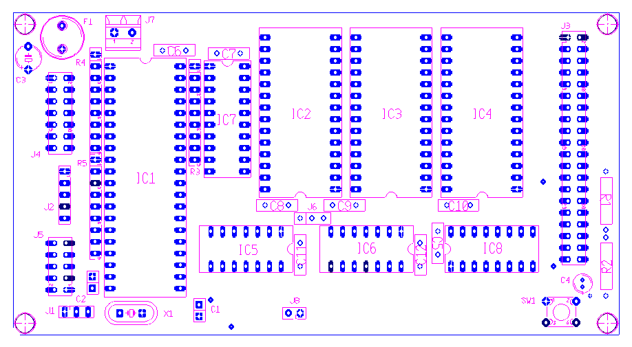
8031 µP DIP40 component layout 131mm x 70mm. R4 and R5 are not required when the 8031 µP P1 and P3 ports have internal pull-up resistors.
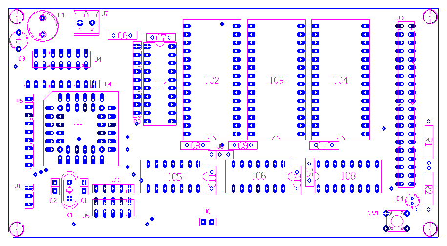
8031 µP PLCC44 component layout 131mm x 70mm. R4 and R5 are not required when the 8031 µP P1 and P3 ports have internal pull-up resistors.
Basic 80C535 µP Development PCB
The basic 80C535 µP pcb (8031 µP compatible) is a development board with no peripherals except for the external memory. Its functionality offers:
- 8-bit CPU with boolean processor, 64K code and 64K data space memory addressing
- 256 bytes on-chip RAM
- three 16-bit timers/counters
- 16-bit reload, compare, capture capability
- 16-bit watchdog timer
- 12 interrupt sources (7 external, 5 internal), 4 priority levels
- stack depth up to 256 byte
- 1 µs instruction cycle at 12-MHz operation
- 4 µs multiply and divide
- one input port for digital input or
- A/D converter, 8 multiplexed analog inputs, programmable reference voltages
- programmable full-duplex serial 5-pin or 10-pin port (baud rate could be provided by one of the timers).
- 8K or 32K external RAM
- 8K, 16K or 32K external EPROM
- 8K, 16K or 32K external EEPROM
- 40-pin peripheral I/O extension bus with 8 chip select lines for I/O addressing
- 30-pin I/O extension bus for 16 general purpose I/O pins and 8 multiplexed analog inputs or 8 digital inputs
- 14-pin I/O connector for 9 (32K EEPROM present) or 10 general purpose I/O pins (J1 1-2 closed)
80C535 µP schematics and layouts
The 10-pin serial interface is compatible with the IF-Module serial interface system as offered by Elektronikladen. Alternatives are offered here.
| Memory map, CS = code space, DS = data space | ||||
|
DS+CS: |
RAM |
32K - 64K |
||
| Bill of Materials | ||||
|
X1 |
X-tal 16 MHz |
1x |
||
Serial interfaces
Four RS232 variants are available: two MAX232 based and two 74HC04 (it only works with 74HC04) based serial interfaces:
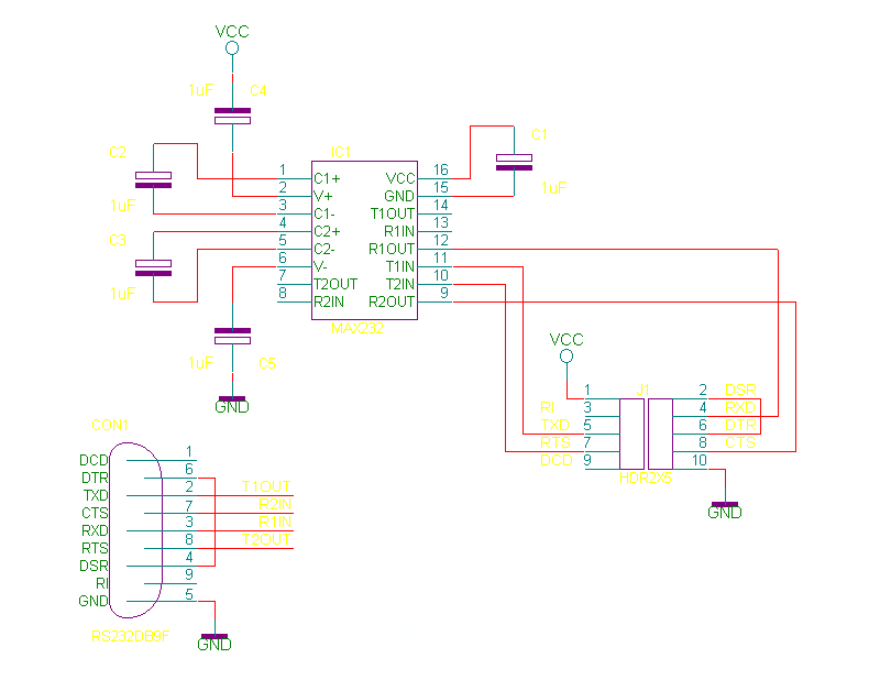
MAX 232, DB9 female connector.
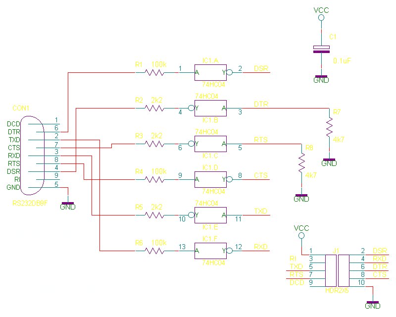
74HC04, DB9 female connector.
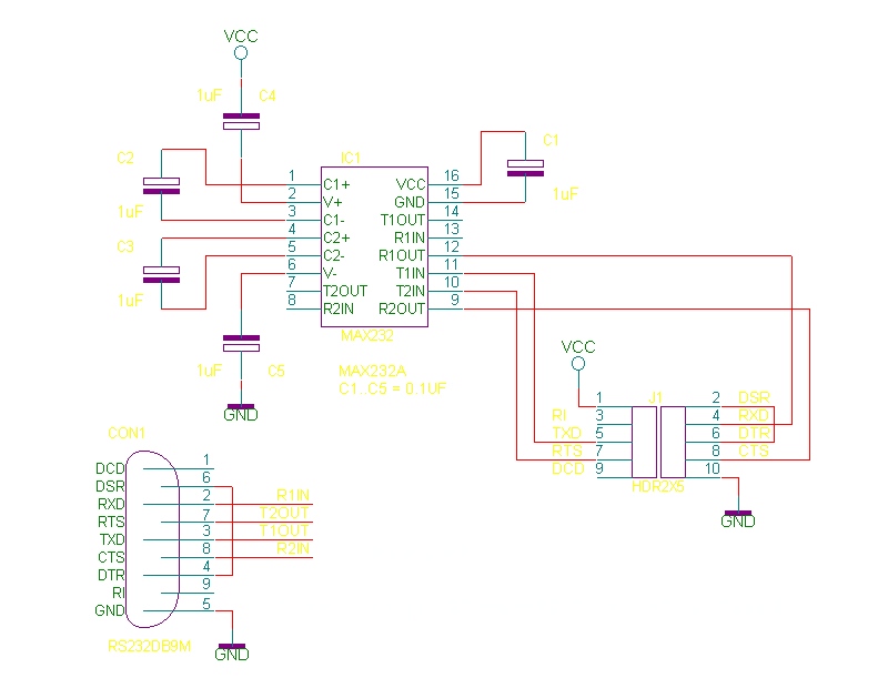
MAX 232, DB9 male connector.
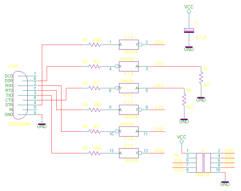
74HC04, DB9 male connector.